Roof Trusses and Loft Framing Overview
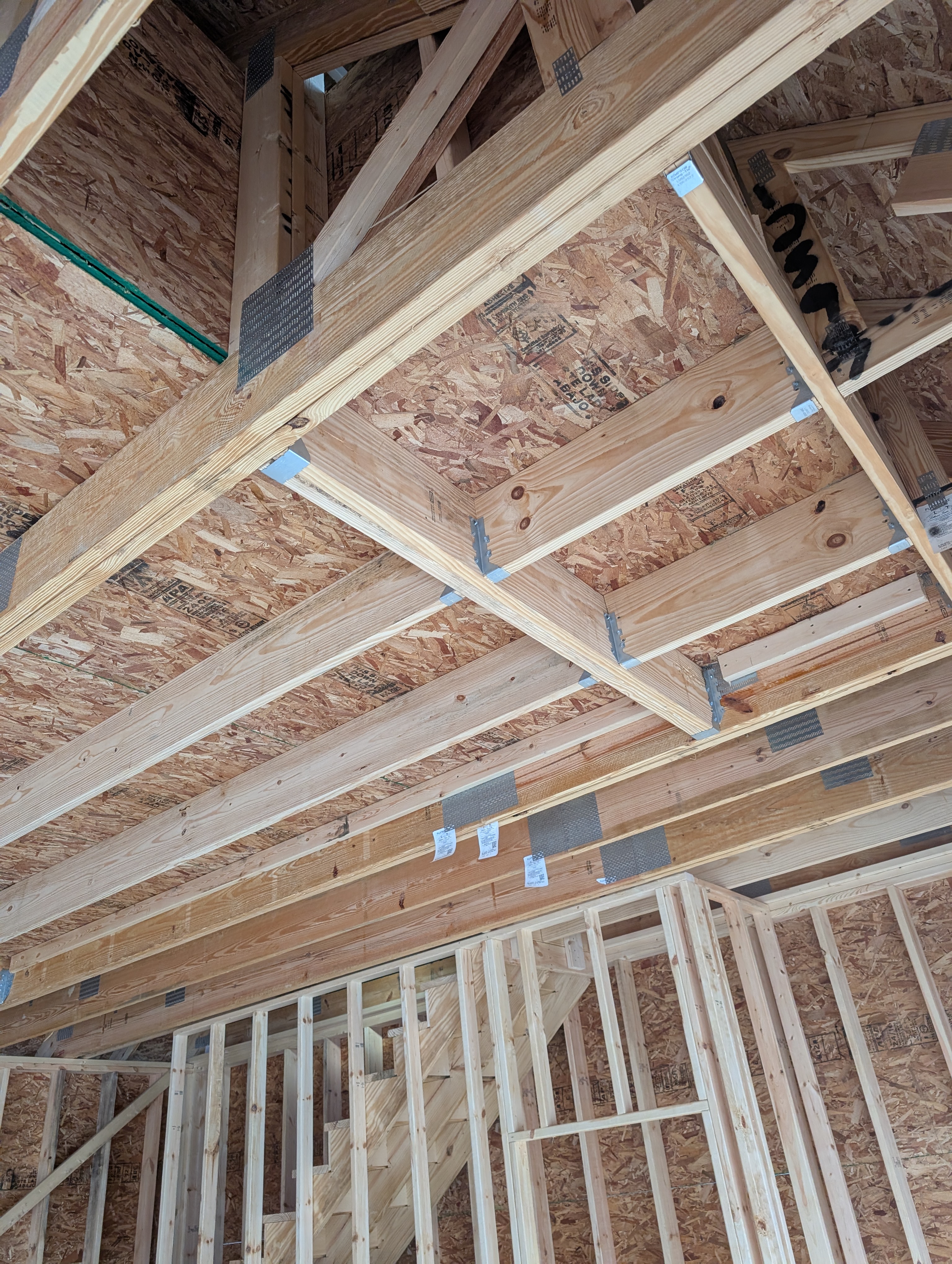
Photo Details
- Date: December 25, 2025
- Time: 3:22 PM EST
- Weather: Cloudy, 21°F. Cold winter afternoon with snow on ground.
- Phase: Framing (Interior Documentation)
- Location: 309 E. 7th St., Clare, MI
- View: Looking up from main garage floor toward roof structure
Description
Wide-angle view looking upward showing the relationship between roof trusses, loft floor framing, and interior wall structure. Photo captures the overall framing geometry for insulation planning, showing how the truss system integrates with the loft level.
Visible Elements
Roof Truss System:
- Multiple engineered roof trusses spanning the building width
- Metal gusset plates (gang-nail connectors) at all truss joints
- Diagonal web members creating triangulated structure
- OSB roof sheathing visible at top
Loft Level Framing:
- Loft floor joists running perpendicular to view
- Simpson Strong-Tie joist hangers (metal brackets visible)
- Loft knee wall studs at partial height
- Main floor wall top plates below loft
Interior Structure:
- First-floor wall framing visible at bottom
- Window rough opening framed in exterior wall
- Temporary diagonal bracing still in place
Insulation Planning Notes
Key observations for insulation strategy:
- Loft ceiling will require insulation between trusses
- Knee wall cavities need insulation for conditioned loft space
- Main floor ceiling open to loft (no insulation needed at loft floor)
- Exterior wall cavities accessible from both levels